Diodes are essential components in electronic circuits, playing a crucial role in controlling the direction of electrical current. Whether you're designing a new circuit or troubleshooting an existing one, understanding how to identify diodes is key.
This guide will walk you through the different ways to recognize diodes based on their appearance, functionality, and characteristics.
From physical markings and testing with a multimeter to understanding circuit symbols, we’ll cover everything you need to know to identify diodes effectively and confidently.
What is a Diode?

A diode is a semiconductor device usually made of silicon used as a one-way switch for current. It drastically limits current in the opposite direction but lets it pass readily in one direction. Many diode circuits applied for different purposes have this essential feature.
Because they translate alternating current (AC) into pulsing direct current (DC), which facilitates power flow regulation, diodes are sometimes referred to as rectifiers. Their type, voltage, and current capacity—the highest voltage and current a diode can safely manage—define their rating.
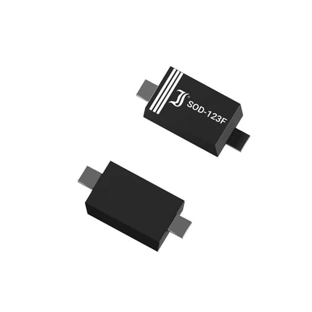
Diodes can be arranged in metal casing, stud mount, plastic case with a band, plastic case with a chamfer, or glass case.
What is the purpose of the diode?

In a circuit, a diode drives the direction of electrical current. Comparable to a one-way valve for electricity, it lets current pass freely in one direction while blocking it in the other.
The diode lets current pass through the anode—the positive side—when a positive voltage is provided, and a negative voltage is supplied to the cathode—the opposing side. Forward bias is how many electronic devices use diodes to regulate energy flow.
On the other hand, the diode enters reverse bias when the cathode has a higher voltage than the anode. In this state, it inhibits current, stopping almost all electrical energy from passing through.
Devices such as power sources depend on this one-way current control, known as rectification since AC must be transformed into DC (direct current) for appropriate use. Diodes are also used to safeguard circuits to prevent harm from reverse current flow and ensure that electrical systems operate only in the intended direction.
How Do Diodes Work?
Two terminals define a diode: the cathode, on the negative side, and the anode, on the positive side. A diode lets current flow when the voltage at the anode rises over the voltage at the cathode by a specific threshold—about 0.7 V for silicon diodes. The diode doesn't conduct current if the voltage difference is less.
Rectification is the act of letting current run in one direction and preventing it from running in the other. Diode circuits, which are used for everything from AC-DC conversion to reverse current protection to radio wave detection, use this capability.
Reverse bias results from an anode voltage below that of the cathode; forward bias results from an anode voltage higher than the cathode voltage. Under reverse bias, the diode approaches breakdown voltage, at which time the current starts to flow as the voltage rises.
Though ordinary diodes may suffer degradation if run in this range, they are useful in surge protection, ESD protection, and constant-voltage circuits. Such uses call for specialized diodes, such as ESD protection or Zener diodes.
How to Test a Diode Using a Multimeter

Two major types are diode test mode and resistance mode for multimeter diode check. While resistance mode might be employed if your multimeter lacks a diode test capability, the diode test mode is the more dependable approach for testing.
Test Mode for Diode Devices
Set the Multimeter in Diode Test Mode: The diode symbol is usually shown as an arrow pointing to a line. Turn the dial to the diode test mode.
Connect the anode from the positive (red) lead to the forward bias and the cathode from the negative (black) lead. For most silicon diodes, a suitable diode should exhibit a voltage drop between 0.5 and 0.8 volts, indicating that it is forward-biased and letting current flow.
Reversing the test leads, link the negative lead to the anode and the positive lead to the cathode. Being reverse-biased and stopping electricity from flowing, a good diode should show "OL" or an open loop.
Resistance Mode
Use the resistance (Ω) setting on your multimeter to examine the status of the diode should it lack a diode test mode.
Make the multimeter resistant mode. Set the dial to resist (Ω).
To test the forward bias, link the negative lead to the cathode and the positive lead to the anode. A suitable diode usually exhibits low resistance between 1000 ohms and 10 Mohms, allowing electricity to pass through it.
Reverse the test leads; the multimeter should display "OL," or very high resistance, indicating that no current flows in the reverse direction.
Interpreting Results
In forward bias, a functioning diode exhibits a voltage drop between 0.5 and 0.8 volts; in reverse bias, "OL."
The diode is defective if the readings in both directions match one another.
Usually, at 0.4 volts, the multimeter indicates the same voltage drop in both directions, so the diode is shorted and should be changed.
Types of Diodes

There are several varieties of diodes, each with unique qualities and uses:
By converting AC to DC, rectifier diodes help simplify current control flow.
Zener diodes provide overvoltage protection. When the voltage crosses a set threshold, it reverses the current.
LEDs, or light-emitting diodes, produce light when forward-biased current runs across them. They are extensively used in indicators and displays.
Fast switching and minimal forward voltage drop of Schottky Diodes make them perfect for high-speed applications.
Often used in sensors and solar cells, photodiodes create electrical currents when subjected to light.
Practical Applications of Diode Symbols in Circuit Design
Essential in circuit designs, diode symbols protect sensitive components and aid in showing how electrical current flows through systems. They are found in many fields, including automotive electronics for voltage control and protection, communication circuits for signal modulation, and power supply systems to change AC to DC. These are some essential places where diodes are indispensable:
Rectifier circuits depend on diodes to convert alternating current (AC) into direct current (DC). Devices needing DC to rely on this conversion.
Diodes clamp and dampen voltage spikes to protect signals, avoiding harm to sensitive electronic components.
In digital circuits, diodes enable the flow of electricity along designated pathways, guaranteeing correct circuit operation.
Diodes are positioned in circuits to block current if the reverse polarity is used, preventing damage from improper connections.
Zener diodes are often utilized as voltage regulators. In reverse bias, they provide essential protection against voltage surges in electronic circuits by keeping a constant voltage across their terminals despite fluctuations in the input voltage.
What's the difference between a diode and a buffer?
Both fundamental electronic parts, a diode, and a buffer, have different uses.
A diode is a semiconductor that essentially blocks reverse current by allowing just one direction of flow. Its main purposes are protection—stopping reverse current flow in circuits—and rectification, converting AC to DC.
Conversely, a buffer is made to pass a signal without changing it while separating many sections of a circuit. Usually employed for impedance matching between several circuit sections, it guarantees the signal's integrity.
A buffer lets a signal pass through without altering its properties, acting more as a signal isolator or amplifier. In contrast, a diode regulates current flow in a designated direction.
Appreciating the Positive and Negative Direction of an LED Diode
LEDs (Light Emitting Diodes) have specified polarity. Hence, proper operation depends on the right connection. The cathode negative side should be coupled to the negative side of the circuit; the anode (positive side) should be coupled to the positive voltage.
Forward-biased current lets the LED emit light by moving from the anode to the cathode. Should the LED be connected in reverse , it will not generate light and may be destroyed over time.
Case Study: Diodes with the Digital Multimeter Fluke 87V
LEDs are sometimes coupled in series on scoreboards. One diode failing may cause the whole segment to darken. Conventional approaches to identifying the problem could take time, and a DC power source and resistor could be called to test every LED.
With a built-in diode test mode, the Fluke 87V Industrial Multimeter makes it simpler to find malfunctioning diodes. Here is the approach:
Make sure that capacitors are depleted and that all power to the circuit is off.
Dial the multimeter in diode test mode.
Recording the measurement, link the test leads to the diode.
Record the second measurement, and then reverse the test leads.
This fast and effective approach helps technicians determine which diodes require replacement, enabling the restoration of scoreboard performance.
Conclusion
Though tiny parts, diodes are essential in contemporary electronics. Their ability to regulate the direction of current opens a significant number of uses. Digital multimeters and other equipment make maintaining and testing diodes simple, guaranteeing electronic circuits' seamless running.